Project Overview
Designed the 3D model and conducted Finite Element Analysis for a statically indeterminate beam as part of a group CEP assignment for ME-302 Solid Mechanics II at NED University. The beam was modelled as an I-section in SolidWorks based on calculated cross-sectional dimensions and imported into ANSYS Mechanical for static structural validation under combined loading conditions.
Challenge
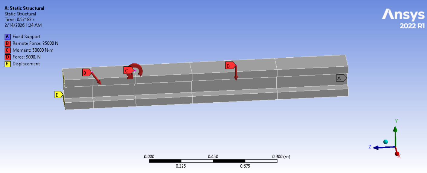
The beam was subjected to simultaneous complex loading — a 25 kN remote force, a 50 kN-m applied moment, and a 9 kN transverse force acting on a 2-metre statically indeterminate span. Designing a cross-section that satisfied both the maximum bending stress limit of 150 MPa and a deflection limit of 50 mm while remaining cost-effective required careful selection of I-beam geometry and material properties before any physical validation.
Solution
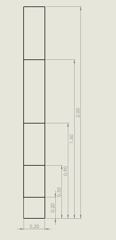
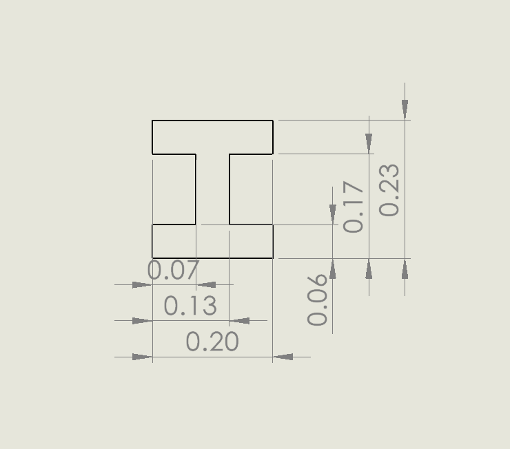
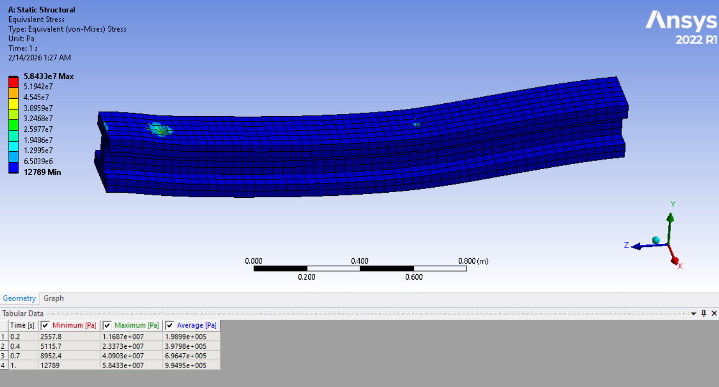
Designed an I-beam cross-section in SolidWorks with a 200 mm flange width, 230 mm total height, and 60 mm web thickness based on a required moment of inertia of 2×10⁻⁴ m⁴. The geometry was modelled as a full 3D solid spanning 2 metres with defined segment lengths. In ANSYS Mechanical, a static structural analysis was configured with a fixed support, remote force of 25,000 N, applied moment of 50,000 N-m, and a 9,000 N transverse force. The simulation confirmed a peak von Mises stress of 58.43 MPa — well below the 150 MPa allowable bending stress — and total deformation within the 50 mm deflection limit, validating the analytical solution.