Project Overview
Designed a shell and tube counterflow heat exchanger in SolidWorks and conducted a Computational Fluid Dynamics simulation in ANSYS Fluent to study the thermal and fluid behaviour of the system. The project was completed independently in 2024 as a self-directed engineering exploration into heat transfer and CFD methodology.
Challenge
The core challenge was accurately modelling the counterflow configuration — where hot and cold fluids flow in opposite directions through the shell and tube arrangement — and setting up a CFD simulation that correctly captured the heat exchange between the two fluid streams. This required careful geometry modelling in SolidWorks, clean mesh generation in ANSYS, and correct boundary condition definition for both inlet and outlet flow conditions.
Solution
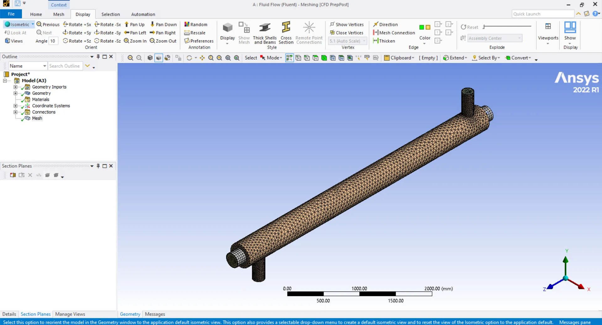
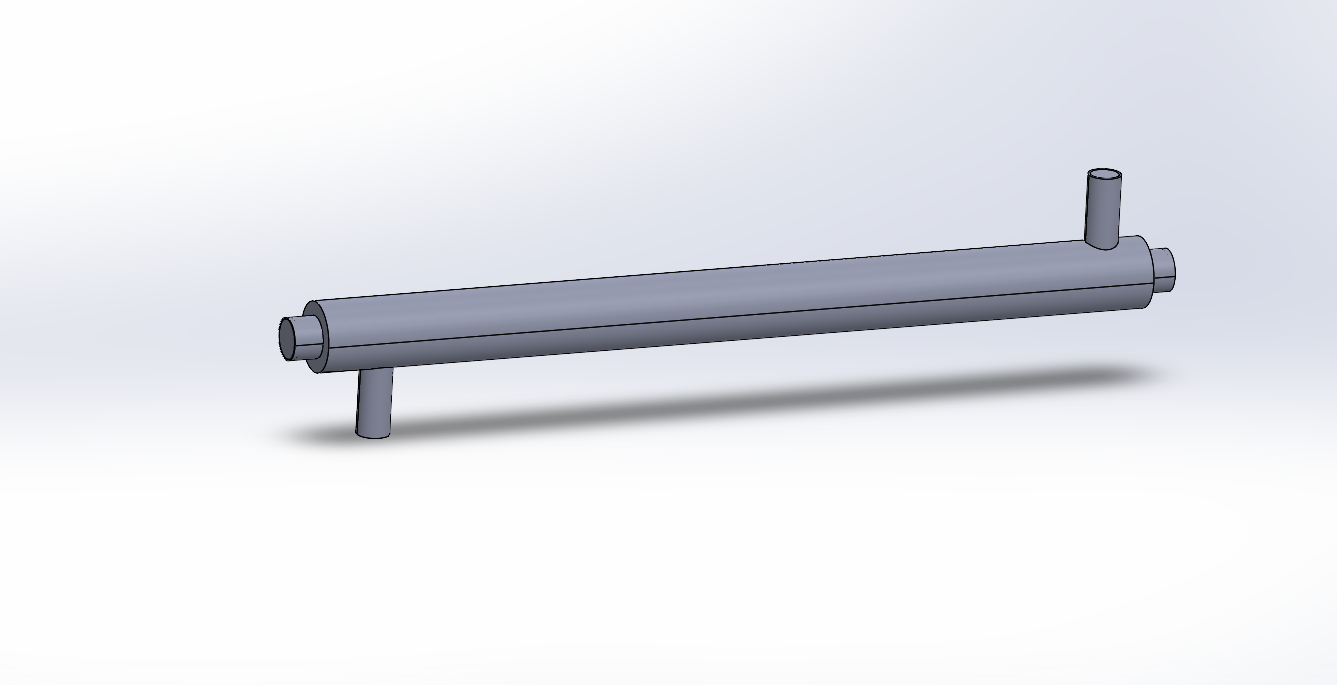
Modelled the shell and tube geometry in SolidWorks with inlet and outlet ports for both the shell-side and tube-side fluid circuits. Imported the geometry into ANSYS Fluent and generated a CFD mesh across the full assembly. Defined boundary conditions for the counterflow configuration — hot fluid entering from one end while cold fluid entered from the opposite end. Ran the simulation and analysed the results to observe temperature distribution, velocity profiles, and heat transfer behaviour across the exchanger length.